On the outside grows the fur side, on the inside grows the skin side; So the fur side is the outside, and the skin side is the inside. - Herbert George Pointing.
Congratulations !!! You've made it this far in the course without any serious injuries. Being this is the last homework assignment (which is due in a week) and knowing ya'll are anxious to get working on your final projects, I have decided to make this assignment short, sweet, and to the point.
. This homework assignment will illustrate
So far in this coarse we have dealt with simple geometric objects consisting of points, lines, and n-gons. At first thought, this knowledge my seem insufficient, simple, and crude until you notice that a majority of real-world objects can be rendered using these same basic geometric primitives. There are however, cases where we require a "richer" set of shapes or curves not easily characterized by a simple primitive. These curves arise because they are aesthetically pleasing or they represent an actual curve found in nature. For example, consider animating and/or analyzing a human foot as it performs the simple task of walking or running; for the dancers in the house - break dancing. The trajectory of the foot can be described and parameterized by a closed and hopefully smooth curve which can yield insight on where the maximum impulsive pressure and torque occur during the activity. For the mechanical engineers in the audience, a specialized curves can arise by some analysis program to yield the best possible design, such as an airplane wing's sweep that provides maximum lift, a cam design, or a car body that is designed based on complex engineering utilities, ease of manufacturing, and what would be appealing to customers. Hopefully, these examples have impressed upon you the importance of "Splining Techniques". In defining a spline curve emphasis must be placed on the distinction between interpolation and approximation of control points, as discussed in class. Whether to use interpolation or approximation depends on the problem at hand and the requirements to satisfy. On the upside, interpolation (Hermite, Natural Cubic, Lagrange) and approximation (Bezier, B-splines, NURBS ) techniques are all related and differ only in the blending function used, and the conditions imposed on the control points. This means you can easily extend your knowledge and understanding from one spline technique to the others. Additionally, although we refer to splines as curves they can easily be extended to generate surfaces - double thumbs up.
This homework assignment was actually motivated by the Jody Foster movie - "The Panic Room". The entire movie takes place inside a three story home complete with a heroine and bad guys, chasing each other all over the house. As you can imagine this poses a problem in providing the movie view continuity in knowing where all the characters are at any given time through various action chase scenes. Surprisingly enough, the director of the move began production by first animating the all scenes in a computer. This provided them with visual tools in which they could experiment and ultimately obtain the best camera angles for a given scene; smart decision knowing actors cost a lot of money and performing multiple retakes of a scene could be quite expensive.
When the going gets tough, the smart get lost - Robert Byrne
You have been contracted by a major motion picture company to design a video camera boom system. The director of the film has expressed that he would like to take advantage of specific camera positions at specified times during the filming of a specific scene. Before you can design the boom system you must write software to generate the trajectory the camera must traverse, given the specific position and time values specified by the director ( a spline interpolation problem with time as an additional dimension). You accept the assignment and they are willing to pay you one-hundred billion dollars and 35 cents for your talent. If successful this would make you richer than Bill Gates ... by 35 cents.
Create an empty console project, call it hw5. Download the following zip file, and unzip the files in your hw5 project directory that you just created. If successful you should have (in addition to the files already created by Microsoft Visual C++ for your empty project) the following files in your project directory:
spline_data.dat is a text file which contains control points and time values in the following format:
line 1: number-of-control points
line2: t0 x0 y0 z0
line3: t1 x1 y1 z1 etc.........
The first line in the file contains the number of control points to read in. Each line after that corresponds to a control point that consists of an (x,y,z) components for camera position and a time of arrival for the camera to reach that position. Note, the time values must be monotonically increasing and the maximum number of control points that can be specified is 50. Since the camera look direction is not specified we will assume it always points towards the origin. Luckily the scene I have generated is located there.
main.cpp contains skeletal code which I am giving you as a stating point. The remaining files deal with loading and rendering objects into the scene. Some objects were created from with an external 3-D modeling package, can you tell which ones ? The files in the data directory contains vertex and material properties, while the library file reads and renders the information contained in these files. You don't need to worry about these files for now, unless your curious on how you could incorporate something similar in your final project.
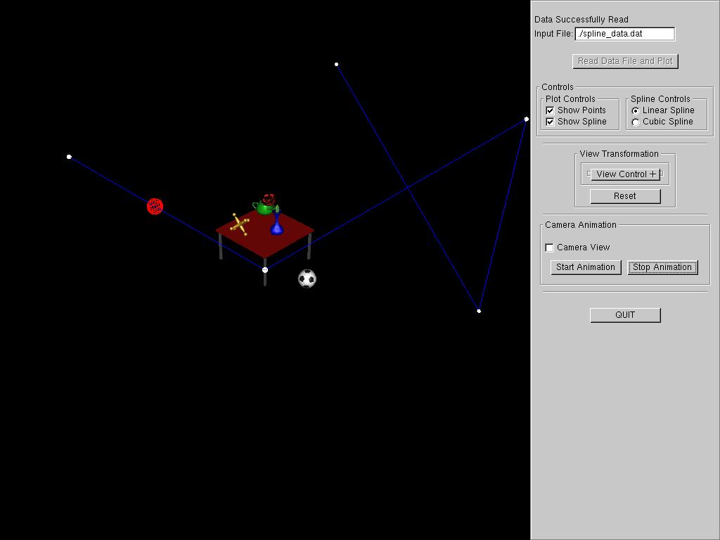
main.cpp once inserted into your project should compile and run, provided the files listed above are present and the executable can open them. If you run the code the following user interface should pop up:
A couple of major features to point out are:
If you haven't figured it out yet, the code is complete except for generating a natural cubic spline as a trajectory for the camera/scene animation. You need to design and implement this code. I will say this one more time .... You need to design and implement code to generate a natural cubic spline. Plotting and animating the camera based on your spline is automatically taken care of, SINCE THE CODE IS ALREADY DOING THAT FOR A LINEAR SPLINE. All you need to do is store the spline coefficients in the appropriate arrays provided. Notice that a linear spline produces mediocre results. Its pretty smooth along the trajectory except at the control points, where we lose C[1] continuity. This fact produces the jerky motion at the knot points when viewing the animated scene in camera view. Minimizing the jerk requires a higher order spline.
The code structure is pretty straight forward ... but involved. The following structures have been defined for you.
| //-------------------------------------------------------------------------- // Define structures to hold our file data and spline coefficients //-------------------------------------------------------------------------- typedef struct { float *a; // spline coefficients a,b,c,d float *b; float *c; float *d; } SPLINE_COEFFS; typedef struct { int numPts; // number of data points read in from input file float *x; // x position float *y; // y position float *z; // z position float *t; // time values .......... SPLINE_DATA data;
// variable to hold our file data |
The spline data is read in by the function ReadDataFile() and stored in structure variable called data. The number of data points is stored in data.numPts. I have allocated the array which stores the data dynamically using the function calloc(), and I use pointers to access the arrays (darn, those pesky pointers). If your confused on how to access the data arrays and and its elements, see ReadDataFile() where I read them in and store them. The Spline coefficients are accessed in a similar manner.
Now, finally we get to what your interested in, where to compute spline coefficients. Basically the function ComputeSplineCoeffs() handles this.
| void ComputeSplineCoeffs(void) { if (gSplineType == CUBIC_SPLINE) { // compute
cubic spline coefficients here
***** Remaining code not shown for clarity ***** |
The first thing we do in this function is test what kind of spline coefficients must be computed. In the code above, the else block shows how you would store the spline coefficients for the linear spline case in the X dimension. Remember a linear spline has already been implemented for you. Implement your natural cubic spline code in the if statement above. Once the spline coefficients have been computed and stored in the appropriate array structure, your pretty much done, except for
Points will be assigned as follows:
| Compile downloaded and provided code. | 30 |
| Implementation of natural cubic spline algorithm. | 50 |
| Comment your code well, provide a comment block at the top of your program. Some of you are starting to slack off. | 10 |
| Connect key 's' to toggle plotting the spline curve and key 'p' to toggle plotting spline control points | 10 |
| Extra Credit | 10 |
| POTENTIAL TOTAL | 110 |
For those who finish early and would like to earn extra credit, describe within your program comment block:
1) Why does an interpolation spline always "bulge out before entering a control point" (5 pts)
2) I would like to specify camera look angle along with position, to pan the camera at each position. How would you extend the program to accomplish this panning smoothly. (5 pts)