
| WHAT IS IT | HOW TO DO IT | LINKS FOR IT |
|
There are two types of signals to be considered within the context of microprocessors:
An analog quantity can be converted to a digital quantity, and vice-versa. Obviously, information is lost whenever this conversion happens. The digital quantity lacks the infinite information which is contained in the analog signal, but much of that information may be unnecessary, if the digital representation contains sufficient information.
For the world of electronics, analog and digital quantities generally exist in terms of voltages. Converting from analog to digital and digital to analog signals can be performed with the use of simple microchips. Many of these chips then communicate with a host computer or microprocessor by serial or parallel means. One advantage of this is that an analog signal can be converted to digital numbers, then sent across large distances in a way by which no more information is lost than the initial conversion. A long wire will tend to pick up ambient noise, which will then be measured as if part of the signal of interest. For example, common noise comes from AC power in a building. The AC power cycles as a sine wave at a frequency of 60 Hertz (60 times per second).
This sine wave then adds to the signal you are attempting to measure. If the sine wave amplitude is similar to your signal, you cannot measure your signal. This proportion is called the signal to noise ratio. There are many steps which may be taken to reduce noise, such as shielding bare wires from electromagnetism.
Each voltage signal which is measured is referred to as a channel. Many microchip analog to digital converters have more than one channel which can be measured. One such chip, which we shall discuss here is the ADC0838, manufactured by linear devices. Some of the important features of the ADC0838 (see the DATASHEET for more info) are:
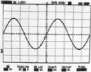
That's 0.000032 Seconds! One may think that is incredibly fast, and yes it certainly is far quicker than you can say 'convert,' but you will see that the speed is necessary. In order to be sure you are measuring what you think you are measuring, a few issues must be considered and dealt with. The first is the speed at which the signal you are trying to measure is changing. If you are trying to measure the temperature change in your coffee while you read this article, a sample rate of once every few seconds will be sufficient to measure the temperature variation. If you are trying to measure the acceleration experienced by a test vehicle colliding with a wall during a crash test, once every few seconds is far too slow, you need at least 1000 times per second (1 kHz) or perhaps faster! In order to measure a signal, and avoid problems, one must sample, or record data points, at twice the maximum rate of change you are interested in. This avoids what is referred to as aliasing. Aliasing is an undesirable phenomenon which can happen when a high frequency signal is sampled at a frequency less than twice as fast. The resulting signal which one thinks one has measured is not a true signal, as evidenced below:
Here we see that as our sample frequency drops below two times the frequency of the sine wave, our measured signal fails to reproduce the sine wave accurately. As we drop the frequency even more, the signal we measure is looks more like a triangle wave than a sine wave.
Low Pass filtersmay need to be implemented to remove higher frequency artifacts from your measurements. A low pass filter, as the name implies, allows low frequency data to pass through it, while 'attenuating' (reducing the amplitude of ) the high frequency aspects of the data. In other words, you measure only the signals you want to measure, and remove what you don't want. This is similar to drinking orange juice with no pulp. You get the juice, but if you don't want the pulp, you filter it out! A low pass filter is implemented as follows:
and the values can be computed from the equation:
The physical package of the ADC0838 which we will use is as follows:
Here is a pin diagram of the ADC0838.
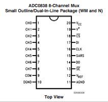
And a description of each pin:
A common connection for using the ADC0838 with the basic stamp II for analog to digital conversion is as follows (R1 is a 10 kOhm potentiometer, our 'variable' input which lets us give a voltage between 0 and maximum voltage drop):
Note1 : +5V is the stamp Vdd, GND is stamp Vss, since in this case our sensors will be powered by the stamp. Consult the ADC0838 datasheet for more info for which ground to use for a separately powered or referenced analog signal source.
Note2 : the connector labelled 'to_stamp' refers to stamp pin connections to the basic stamp Digital I/O's (0-15). We will use 1-5 here
Note3 : We are only using channel 0 in this example, but all channels can be connected to different analog sources for different measurements
There are a few things that must happen for a successful read from the ADC0838. These are the steps:
Here is a timing diagram equivalent to what is in words above:
The following table is how we set up the adc0838 for which channel to use and whether to be single-ended or differential (the codes we are interested in are the mux addresses. So if you wanted to set up your sample for single-ended, channel 0, you would send 11000 with the shiftout command like this: SHIFTOUT DIO, CLK, 1, [%11000\5]):
A Quick Program to read the analog voltage across the potentiometer:
|
'declare variables and constants adcBits VAR BYTE
main: 'Channel 0, single-ended measure, the
first bit is a start bit, the last four 'Get the sample, 8 bits expected, Most
significant bit first 'convert to a 10x voltage and display
on the debug screen, ie 00 to 50 would equal 0.0 to 5.0 Volts 'Start over |
If you want to measure an analog voltage, just connect the analog signal to the appropriate pin, referenced to COM (ie, + signal to Ch#, analog ground to COM), or differential referenced to Ch-. Then program the ADC0838 with the appropriate setup codes.
Impedance is a big issue. One can consider impedance to be similar to resistance. Problems can occur from various related issue to impedance. If the impedance of the signal passing through circuits is not matched properly, spurious readings can result from energy waves reflecting through the circuit. This is a similar phenomenon to a wave bouncing off the wall of a pool and reflecting back.
Check the voltage range of the input signal. It must be within the set-up of your chip, or you risk damaging your ADC0838 chip.
Don't forget to low pass filter your input. Decide on the fastest signal you'll need to measure and cut off the rest.
Realize that there is more happening than what is described here, consider this document as a simple introduction to data acquisition. It gives you the tools you need to get started, but please continue to expand your knowledge. Otherwise when problems arise, they may take a long time to understand when they may be simple issues.